Diode-OR UPS

I recently put together what is basically a small UPS. It’s simple, made up of three diodes and some resistors, and lets you trickle charge a battery while power something and then seamlessly switch to the battery if the power source goes out.

This was actually built just for charging a small lithium iron phosphate (LiFEPO4) battery from a car cigarette lighter plug while power something, but it could be used for a lot of things. Here’s the schematic:

The schematic of the Diode-OR UPS.  It shows the positive connection from a power source, Vin+, connecting to the positive connection of an output, Vo+, through diode D1.  The positive connection of a battery, B1, also connects to Vo+, through diode D2.  Vin+ also connects to the positive of B1 through diode D3 and resistor R1.

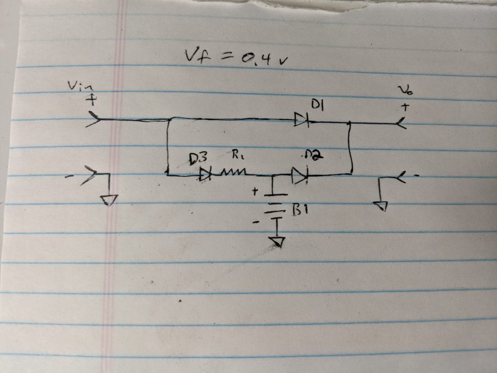
Basically, current can flow from the input to the output (Vin to Vo) through D1, or from the battery to the output through D2. If power is present, the battery can be charged through D3 and R1 – R1 sets the current, based on the voltage difference between the source and the battery, and the forward drop in D3.

This type of circuit is great because it’s simple, and it accomplishes a lot of what you’d like: it lets a source power something and trickle charge a battery, and switches the load to the battery if the source drops. It’s passive, and should just work. On the other hand, the battery is being passively charged, and it kind of relies on the voltage of the source to regulate it. There’s also the diode drops, which for a Schottky diode is around 0.4 V. For a normal silicon diode, it would be higher, around 0.7 V.

You could improve this with an ideal diode circuit, where you could basically control a MOSFET in place of each diode to turn on and off when the diode would. This is more complex, but you almost eliminate the diode drop. If you needed something like this to handle more than a few amps, that’s probably not a bad idea.

Another option, and probably the ideal one, is to use a power converter, at least to charge the battery. A non-inverting buck-boost converter would do this, and allow you to control the charging current regardless of the voltage of the source and B1. You could have it do a proper charge of the battery, bulk/absorb/float for lead acid, or bulk/absorb for LiFEPO4 (or whatever scheme that battery chemistry calls for). A fancier converter (or converters) might supply a constant voltage to the load at the same time.

Still, for something small, the simplicity here is nice. It could work well for something like holding up a Raspberry Pi or other single board computer, for instance. One thing to note is that most diodes in a TO-220 or TO-240 or similar case often are not electrically isolated. You can get a heat sink with an electrically insulating thermal pad; I have one I garbage picked a while back.

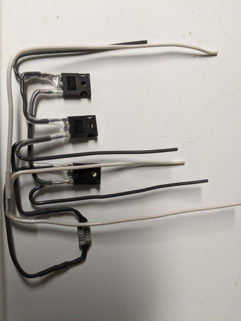
Here is what the circuit looks like, assembled:

The circuit shown in the schematic, wired together by soldering bits of Romex wire to the components.

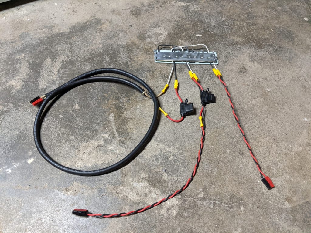
I put it in a heat sink and attached some leads with Anderson Powerpole connectors, like the following:

Note that I did alter the resistors to get a little more charging current. The pictures show two 2.2 ohm resistors in parallel (for 1.1 ohms), but I added two 0.9 ohm resistors in parallel as well, for about 0.32 ohms total. The diodes have about a 0.6 V drop under load, so from my car I was able to get around 1.75 amps into a LiFEPO4 battery, while the car is running. This will vary a little, and keep in mind that if your battery is at a lower state of charge you’ll get more current initially.

Goings On

I wish I had some progress to post about, but I will take a few moments to just talk about some scraps of things.

I’m seriously considering moving this blog to a static site, and have been looking at Hugo. I like the idea of composing posts in a text editor, and then regenerating the site when neede

d. I would probably integrate this blog (or a blog like thing) with the front page, ie have a similar layout, style, etc., and maybe add more static-type pages. I might even stop using the wiki, which was kind of my first thought of how this would go: Blog for routine or semi routine updates, wiki for more ‘permanent’ stuff, like how-to guides. I may just keep the wiki around.

I had considered writing my own static site generator, probably throwing something together in Perl. I’m not sure it’s worth doing that. One of the drivers for this was an idea I had about a system to accept comments via email, which I could integrate with my own static site generator. I may just look at doing something with Hugo for that, we’ll see.

This blog does get a decent amount of comments, but most (practically all) of them are spam. I could probably just not bother with it at all, but in the days of my whatsmykarma.com site, some legit comments actually would trickle through. I’ll have to see. I’m going to have to play with Hugo quite a bit, then look at migrating away from WordPress.

I’ve had some electrical projects in mind for a while, the first of which is a buck converter, which I’ve posted about before. One of the parts I was using (a MOSFET) doesn’t seem to be available, so I’ll probably just pick a new one. At this point I need to work on the layout, so I’ll have some KiCad work ahead. That should be fun.

The point of that is to not just design the buck converter, but also do the controls. And layout… And conceive of it as a ‘product,’ not just a circuit I put together. In other words, a box with terminals that will have usefulness.

This leads me to my other project, significantly more of which remains in my imagination right now. And that is an inverter/charger – a power inverter that can also rectify, acting as a battery charger. Kind of like a UPS, but not exactly uninterruptible. I mean, it should be, ideally, but the intent is more for seamlessly switching AC loads to another source and charging a battery, as opposed to keeping computers from going down. Think off-grid power system verses data center application. (Of course, there’s overlap in terms of the technology and applications.)

The first incarnation of this would go from 12 VDC (nominal) to 120 VRMS AC, sine wave output, at about 250 watts. There are a couple reasons for this project:

  • Learning, getting some experience
  • Usefulness, no one really makes a small inverter/charger like this, and I’ve thought it would come in handy
  • Progress, toward an even bigger one
  • Putting a design out there, there should be more practical examples of power conversion available. Maybe even an open source inverter project?

Anyways, more to come, maybe.