The Solar Pi is an idea I had for a project/concept art project: a Raspberry Pi powered directly from a solar panel, hosting a website. When the sun is down, the site isn’t available. There are other solar powered websites out there, but forgoing storage is an interesting idea.
It wouldn’t have to be a Pi, other single board computers could work. The key is that the load is light enough that a solar panel itself can power it without much reserve, over a reasonable period during the day. With a larger panel, even during overcast days you might be able to keep it running somewhat. The idea is to see how useful you can make this without introducing a battery, although I’m considering a supercapacitor to provide enough storage to shutdown gracefully, and handle a single cloud going overhead.
Spiritually, this is similar to things like solar water pumping off-grid: the sun powers the pump whenever it’s out, and you pump water into a tank for use. That’s your energy (and water) storage. Or, a solar vent fan. Conventional grid-tied solar is like using the grid as a battery, although if you time your loads right you can end up using it this way too.
This has gotten me thinking about a couple things. For one, maybe running a mail server too? Email should, in theory, work if a receiving server becomes unavailable. It would be neat to include this as well.
Another idea: what about leveraging something like syncthing? The website could be shared on the Pi, and then others would just download it when it’s online. Not only that, but users could help distribute it as well.
Amusingly, given my home network, the site would probably sit behind a proxy. In other words, another web server and mail server that would relay to the Pi. These would almost certainly be powered from the grid, although I may tackle that as an other project. It kind of takes the starch out of the initial proposal, but from my perspective at least it’s kind of fun to set this all up.
I’ve touched upon Product Lifecycle Management (PLM) systems at work. The general idea makes sense, you have your thing, the subassemblies, and all the parts that go into them. And documents and whatever else. And while in big companies you end up with complex webs of objects within these systems which can sometimes feel offputing, the idea makes sense.
I’ve got a couple things going on with KiCad projects now. One is a DC-DC converter I’m throwing together, to get practice with DC-DC converters, and one is going to be a simple power/energy monitor. Both microcontroller-driven, both low voltage (12, 24, or 36 VDC nominal systems). I like KiCad, and I get that there’s a workflow associated with it in which one associates smaller things like generic passives with the design when it’s done. I however have gotten into the habit of using atomic parts – I create a part for things like a particular resistor or capacitor, in addition to bigger things like a microcontroller.
I’m not sure I need (or want) a full-blown PLM system like I’ve used at work. But, I’ve been daydreaming about something kind of similar. KiCad works on plain text, so it should be easy to script the creation of new parts. At least, for a lot of common ones, it’s a little more complicated when you need a custom symbol or footprint, but still. The other angle here is keeping track of what’s available, which is a problem thanks to all the supply chain issues going on. Digikey and Mouser, two distributors I tend to use, both have APIs where you can query for info about parts. So, I envision a script that takes a part number, grabs information about the part from one of these distributors or a different one, and sticks it in a database.
This could be something of a layer beyond KiCad then. So maybe it coalesces several 1k ohm resistors into a generic part to plop in. Maybe it queries the distributors every day and updates stock. Maybe something about tracking my own supply as well.
I may start to look at this between projects. I don’t know if it would a web app, a commandline-only thing, or heck, maybe an excuse to learn Qt. Probably, it would be best to divide this into chunks, so I don’t get stuck on producing something and get my other projects (which this would supposedly help) blocked. But it’s something to think about.
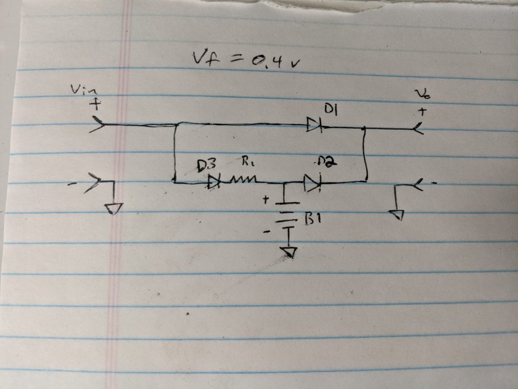
I recently put together what is basically a small UPS. It’s simple, made up of three diodes and some resistors, and lets you trickle charge a battery while power something and then seamlessly switch to the battery if the power source goes out.
This was actually built just for charging a small lithium iron phosphate (LiFEPO4) battery from a car cigarette lighter plug while power something, but it could be used for a lot of things. Here’s the schematic:
Basically, current can flow from the input to the output (Vin to Vo) through D1, or from the battery to the output through D2. If power is present, the battery can be charged through D3 and R1 – R1 sets the current, based on the voltage difference between the source and the battery, and the forward drop in D3.
This type of circuit is great because it’s simple, and it accomplishes a lot of what you’d like: it lets a source power something and trickle charge a battery, and switches the load to the battery if the source drops. It’s passive, and should just work. On the other hand, the battery is being passively charged, and it kind of relies on the voltage of the source to regulate it. There’s also the diode drops, which for a Schottky diode is around 0.4 V. For a normal silicon diode, it would be higher, around 0.7 V.
You could improve this with an ideal diode circuit, where you could basically control a MOSFET in place of each diode to turn on and off when the diode would. This is more complex, but you almost eliminate the diode drop. If you needed something like this to handle more than a few amps, that’s probably not a bad idea.
Another option, and probably the ideal one, is to use a power converter, at least to charge the battery. A non-inverting buck-boost converter would do this, and allow you to control the charging current regardless of the voltage of the source and B1. You could have it do a proper charge of the battery, bulk/absorb/float for lead acid, or bulk/absorb for LiFEPO4 (or whatever scheme that battery chemistry calls for). A fancier converter (or converters) might supply a constant voltage to the load at the same time.
Still, for something small, the simplicity here is nice. It could work well for something like holding up a Raspberry Pi or other single board computer, for instance. One thing to note is that most diodes in a TO-220 or TO-240 or similar case often are not electrically isolated. You can get a heat sink with an electrically insulating thermal pad; I have one I garbage picked a while back.
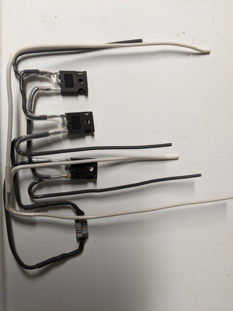
Here is what the circuit looks like, assembled:
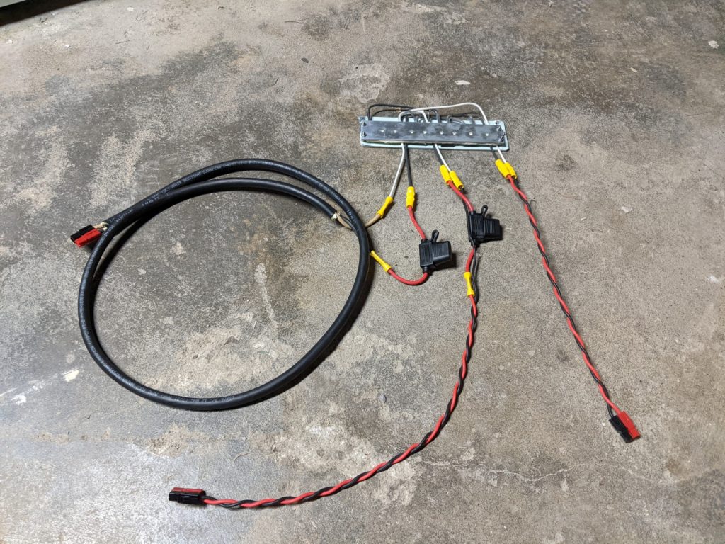
I put it in a heat sink and attached some leads with Anderson Powerpole connectors, like the following:
Note that I did alter the resistors to get a little more charging current. The pictures show two 2.2 ohm resistors in parallel (for 1.1 ohms), but I added two 0.9 ohm resistors in parallel as well, for about 0.32 ohms total. The diodes have about a 0.6 V drop under load, so from my car I was able to get around 1.75 amps into a LiFEPO4 battery, while the car is running. This will vary a little, and keep in mind that if your battery is at a lower state of charge you’ll get more current initially.
As if I needed another project, I had been tossing something around lately regarding renewable energy and the web. Low Tech Magazine, which showcases what it considers old and forgotten technology, has an edition of their website available served from a Raspberry Pi run entirely off-grid. Their setup consists of a Pi powered from a solar-charged battery, and they make it a point that depending on weather, that site may not actually be available at all.
I think that this is an interesting concept, although I’ve been tossing around the idea of taking this further. Rather than try to keep a small web server running all the time completely on solar power, what about running it only when the sun is out? In other words, whenever enough sun hits a panel to produce enough power to keep a Raspberry Pi going (about 3 watts, say). With a large panel, this means it could stay up even when it’s cloudy.
I’ve been playing with off-grid solar for years in a hobbyist capacity, and first wondered about this when seeing the green ‘charging’ light on my charge controller turn on even on a clear night with a bright moon. That is, with enough panelage, can a useful amount of power be extracted even in low light? And what ways are there to utilize solar power without trying to store it?
The system, in my mind, would be relatively simple: A photovoltaic panel, one meant for charging a 12 volt battery, would feed a Raspberry Pi via a buck converter. When there’s enough sun to keep the Pi running, it runs. When there isn’t, it shuts down. The converter would help to match the panel’s output to the Pi, supplying it with a constant 5 VDC. With a large enough panel (>20 watts?), it should be able to put out the required 3 or so watts over a range of weather conditions.
I’m wondering about some other bells and whistles, like somehow predicting when night is about to fall, and gracefully shutting down the Pi. And monitoring voltage and current as well. I may take this as an opportunity to design my own buck with some of this built in, but I think an off-the-shelf converter would work as well.
Anyways, I’m not sure when I’ll get to this, but it’s just a thought. I’m not sure how useful it will be, but it could be kind of fun.
I wish I had some progress to post about, but I will take a few moments to just talk about some scraps of things.
I’m seriously considering moving this blog to a static site, and have been looking at Hugo. I like the idea of composing posts in a text editor, and then regenerating the site when neede
d. I would probably integrate this blog (or a blog like thing) with the front page, ie have a similar layout, style, etc., and maybe add more static-type pages. I might even stop using the wiki, which was kind of my first thought of how this would go: Blog for routine or semi routine updates, wiki for more ‘permanent’ stuff, like how-to guides. I may just keep the wiki around.
I had considered writing my own static site generator, probably throwing something together in Perl. I’m not sure it’s worth doing that. One of the drivers for this was an idea I had about a system to accept comments via email, which I could integrate with my own static site generator. I may just look at doing something with Hugo for that, we’ll see.
This blog does get a decent amount of comments, but most (practically all) of them are spam. I could probably just not bother with it at all, but in the days of my whatsmykarma.com site, some legit comments actually would trickle through. I’ll have to see. I’m going to have to play with Hugo quite a bit, then look at migrating away from WordPress.
I’ve had some electrical projects in mind for a while, the first of which is a buck converter, which I’ve posted about before. One of the parts I was using (a MOSFET) doesn’t seem to be available, so I’ll probably just pick a new one. At this point I need to work on the layout, so I’ll have some KiCad work ahead. That should be fun.
The point of that is to not just design the buck converter, but also do the controls. And layout… And conceive of it as a ‘product,’ not just a circuit I put together. In other words, a box with terminals that will have usefulness.
This leads me to my other project, significantly more of which remains in my imagination right now. And that is an inverter/charger – a power inverter that can also rectify, acting as a battery charger. Kind of like a UPS, but not exactly uninterruptible. I mean, it should be, ideally, but the intent is more for seamlessly switching AC loads to another source and charging a battery, as opposed to keeping computers from going down. Think off-grid power system verses data center application. (Of course, there’s overlap in terms of the technology and applications.)
The first incarnation of this would go from 12 VDC (nominal) to 120 VRMS AC, sine wave output, at about 250 watts. There are a couple reasons for this project:
Learning, getting some experience
Usefulness, no one really makes a small inverter/charger like this, and I’ve thought it would come in handy
Progress, toward an even bigger one
Putting a design out there, there should be more practical examples of power conversion available. Maybe even an open source inverter project?
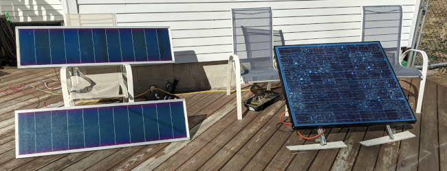
Today is the first day of spring here in the Northern Hemisphere, and it’s quite sunny out. I have about 164 watts of solar between three panels, just sitting on my deck. They are charging an old (~12 years) 49 Ah AGM battery in my garage, which still holds something of a charge but not quite what it used to.
Two 32 watt panels (left), and one 100 watt panel (right). Yes, the deck needs work.
Where I live, electricity is pretty cheap and reliable (municipal coop), and it’s bought from hydro and nuclear generation. This system has evolved over time, and it’s mostly a hobby. However, I wonder about making better use of the power I get from it.
The obvious answer is to try to grid tie these (or other) panels. That would require an appropriate inverter, plus professional installation, approval, etc. It makes sense in a lot of ways, since that way the panels get to run my entire house by virtue of tying into the main breaker panel. Not to mention that these are mismatched, and I’d need to find an inverter that could handle a conglomeration of 12 volt panels (the big one can actually be rewired for 24 volts). I’d rather not use one of the PowerJack inverters, although admittedly I haven’t looked at other grid tie inverters besides from seeing those on Youtube here and there.
I’d like to keep this system off-grid – like I said, my power is cheap, and I’m not sure a big grid-tied array would make sense just from that standpoint. But honestly, I love messing with a small independent system, and it has a few advantages:
Obviously, it’s a source of backup power, and it’s pretty convenient for lighting and phone charging. Power outages aren’t frequent enough that I’m thinking about getting a generator to keep the fridge going, but just having a little bit of reserve is nice.
It’s a source of DC power. I have an amateur radio license, and most ham gear runs from 12 VDC. This is a little tricky since the system is in the garage, but I will get to this.
It’s a way to experiment with… Off-grid systems! Other projects I’ve had kicking around in the back of my head for years directly apply here, and so it makes sense to have an actual application for them. Examples include various DC-DC converter ideas, as well as a DC-AC inverter.
I’ve been thinking about how to upgrade this system. Like I said the battery is old, but it works well enough as a buffer that it’s not completely useless. The charge controller I have is a Morningstar ProStar 30, which is PWM. I could enter the 21st century and get an MPPT controller, and squeeze out an extra amp or so into the battery. I did get a 300 watt true sine wave inverter (the modified sine wave one I had was the victim of a flood), which is nice, but this will eventually be replaced by a homebrew solution.
Of course, this is a lead acid battery, and I’ve also been looking at LiFePO4 as well. This technology is intriguing, given that while it’s more expensive up front it lasts longer in terms of deep cycles. (Lead acid, even deep cycle, lasts longer with shallower cycles.) That said, while I haven’t done an in-depth analysis, it seems that if you’re going to lead a battery float most of the time like in a UPS, lead acid might still be the way to go cost-wise. This of course depends on the quality of the charger, for instance I wouldn’t trust a cheap UPS unit to be a shining example of lead acid charging.
All this aside, something I’ve thought of quite a bit is the idea of siphoning excess power off to do something useful. If I’m not going to grid tie, then I need to get a little creative. The idea is to minimize actual cycling, so ideally the load here would be something that could be served during the day when there’s sun.
DC Distribution
I should take a moment to note that wiring your home for low voltage DC isn’t always the greatest idea. It sounds great when you think of devices running from 12 or 5 VDC anyways, by means of a wall cube or a brick, and that you could avoid using an inverter to do an extra conversion step. (Kind of two steps, when you realize that with a low voltage system, the inverter needs to step battery voltage up to a high enough DC voltage to make the 120 VRMS sine wave, or whatever it would be in your area.)
Contrary to what some think, AC doesn’t inherently travel over long distances better. In fact, it incurs reactive losses, since by nature the voltage and current are changing. But sending a lot of power over long distances does require high voltage, since that means less current for a given amount of power. AC makes this easy by means of a transformer, basically wire wrapped around an iron core. Pretty simple, for certain values of simple.
Thanks to modern power electronics, you can of course step DC up and down too. In fact, a lot of household devices do this, and rectify DC and use a switching power supply to get a lower voltage. It will probably still end up using a transformer and pulse the DC into it, but you can do that at a high frequency which means that the magnetics can be smaller. A transformer for, say, 20 kHz can be smaller than one for 60 Hz. However, this all requires more supporting circuitry – power transistors to do the switching, capacitors, inductors, and transformers, some kind of controller, etc. High voltage DC is used for transmission, since you can avoid reactive losses, but having to address some of this means that it’s used where the expenses of the transmission line would outweigh the cost of the added rectifier/inverter station.
There’s another issue as well. The reactive losses I mentioned essentially resist changes to the flow of current, which obviously is an impediment to AC. But with DC, it’s a different kind of impediment. While they will resist the current ramping up, they can also resist ramping it down. If you have a fault of some sort, the inductance in a wire will try to keep the current flowing. It does this by jacking the voltage up.
This is something you exploit in, say, a buck or boost converter, where you switch a power source into an inductor. The inductor raises or lowers the voltage using the energy it stores in its magnetic field. However, while an inductor is a part you might design into a circuit, a length of wire is also an inductor. If you want to stop current from flowing in a DC circuit, you need to respect that.
Practically, this means that you need DC-rated switches, connectors, and overcurrent protection. This exists, but it’s not as common as what you can get at say Home Depot. (Actually, Square D QO breakers do have a DC rating, I believe. Double check this.) And if you’re using, say, 12 or 24 VDC, you need bigger wire – at 12 volts, for instance, a 100 watt load is about 8.3 A. This means you need to make sure you have solid connections, as pushing high current through a bad connection can cause it to heat up. And then unless you use huge wire, you have to deal with voltage drop.
Of course, high(er) voltage DC is one possibility. Off-grid solar systems typically go up to 48 VDC nominal, which is easier to deal with. You could keep throwing 12 volt batteries in series and end up with 120 VDC, but that kind of compounds the problems I mentioned earlier – now you have a high voltage which can push even more current through a given resistance, so you have that plus the effect of the wiring inductance in the event of a fault. 120 VDC is used in some applications, and it’s not as if it’s impossible to work with, but I wouldn’t just plug my home wiring into it unmodified.
Where to Use DC
Maybe you’re willing to take on the engineering project of wiring a house for DC, low or high voltage, and spend the money on huge wire and appropriately-rated devices. Most likely, though, using standard off-the-shelf parts and readily-available expertise for AC wiring is the way to go. That said, it’s worth considering using DC in certain cases, in my opinion.
A tiny system, maybe a portable one, where you want to run a couple lights and charge your phone. This might be something that fits into a backpack. Maybe it’s just a battery and a cable with a plug of some sort.
Something like a small cabin, with a short wire run to the loads. Maybe the battery is close to say a water pump, a light fixture, etc.
A system which isn’t too far from loads, but most everything just runs on DC anyways. (I’ll get into this one more soon.) An example is a ham radio setup, although this could be debatable. It might make sense to simply use an inverter and have that drive a benchtop supply to run your shack.
A DC light fixture for the room where the rest of your system is. That way if your inverter goes down, you can troubleshoot it.
The third point is something I’ve thought about – my system is in my garage, but I have ham radio gear in the second floor of my house. Additionally, I have networking gear in the basement, much of which could run off of 12 VDC. So while I wouldn’t want to rewire my house to swap too many circuits to 12 volts, how could I bring some power from place to place, and selectively siphon off excess from the solar?
Low-Power DC Transmission
So now I’m going to go against my own advice, and try to move DC to a different area of my house. 🙂 To do this, I’ve been kicking around a DC-DC converter, really a buck converter, that would work bidirectionally. That’s for flexibility, so that I can use the same one in two places.
So it might go like this: Step 12 VDC from my battery in the garage to say 36 VDC, and then run that into my basement. Use another converter in reverse to bring it back down to 12 VDC. That means a three-fold reduction in current. It also means needing to use proper fusing, of course. But it would also be non-permanent and easily undoable.
Actually, the main reason for this is to design and build the converter, to prop my own skills. There’s designing it, laying it out on a PCB, and doing the controls for it (microcontroller project!). And I’m interested in the idea of controlling this to, for instance, run in parallel with a standard power brick supplying an industrial PC I’m using as a server, and basically take load off the grid. So it’s kind of like a grid-tie inverter, without the grid-tie.
Obviously, this may not be the most practical thing for most people, I just happen to be the type of weirdo who thinks it might be fun. I will post more as I explore it.
Cat
George is an indoor creature, but he used to be a stray. Now that it’s sunny he has spring fever, and he’s tried to escape once or twice. I won’t let him, and he usually does okay staying inside, but I do pick him up now and then and walk him around outside. I also leave the door open to the screen so he can sit and listen to the birds and sniff.
George, my gray cat, gazing out the screen door on a beautiful spring day.